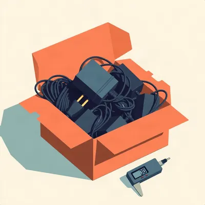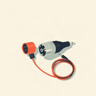
So Daniel sent us this one — and I have to say, it's the kind of question that sounds simple until you actually start poking at it. He's got a ToughBuilt tool belt system, the electrician's pouch, and he's carrying the usual suspects: phone in the holster, power bank, USB-C flashlight in its slot, sometimes a drill. His days are long, he's working from wake-up to lights-out, and he wants to charge everything right on the belt — one cable to the wall, each device getting exactly the voltage it needs. The failure pattern he's noticed is that multi-port chargers have pre-set delivery on each outlet, which rarely matches what his specific devices want. So he's asking: can you DIY a bespoke charging station configured to your exact carry? Or is there an off-the-shelf configurable charger that lets you set per-port voltage?

This is exactly the kind of problem that looks like a convenience question but is actually an electrical engineering puzzle. And Daniel's identified the real tension here — most people think "more ports, more power, done." But USB-C Power Delivery is a negotiation protocol, not a dumb pipe. Every time you plug in a device, there's a conversation happening on the configuration channel line — the CC line — between the charger and the device. The charger says "here's what I can offer," the device says "I'll take that one," and they shake hands. The problem Daniel's hitting is that in a multi-port charger, that conversation gets complicated fast.
So walk me through what's actually happening inside one of these chargers when I plug in three devices. Why can't it just give each port whatever voltage it asks for?
The short answer is money and silicon. Most multi-port chargers share a single power stage — one transformer, one set of switching transistors, one feedback loop. When you plug in multiple devices, the charger has to split that single power budget. The typical approach is fixed allocation: port one gets up to forty-five watts, port two gets up to twenty watts, and that's hard-coded in the firmware. The voltage on each port is determined by what the device requests from the limited set of PDOs — Power Data Objects — that the charger advertises. So if your flashlight wants nine volts at two amps, but the port it's plugged into only advertises five volts and twenty volts, you either get slow charging or you get nothing.
And that's where the over-voltage risk comes in. If the charger advertises twenty volts and the device's protection circuit isn't robust, you could be shoving four times the expected voltage into something designed for five.
And here's the thing most people don't realize: USB-C PD negotiation is per-port, not global. Each port has its own CC line, its own set of advertised PDOs. But in a consumer charger, the ports aren't truly independent. They're multiplexed onto a shared power stage. So even if port one is advertising nine volts and port two is advertising five volts, the actual DC-DC conversion is happening in one place, and the output is being routed through load switches. The charger can't simultaneously output nine volts on one port and five volts on another unless it has independent buck converters for each port — and that costs real money.
So what Daniel's really asking for is a charger where each port has its own independent PD controller and its own buck-boost converter. Which is essentially four separate chargers in one box.
Right. And that exists — but not in the form factor he wants. Lab bench power supplies with multiple USB-C outputs do exactly this. The Riden RD6018 or the Siglent SPD series have fully independent channels. But they're not fitting in a ToughBuilt pouch. They're desk instruments.
Let's talk about the trigger board approach, because that's the first thing that comes up when you search for "DIY USB-C voltage control." You can get these little boards from Adafruit or SparkFun or the usual AliExpress suspects — they have DIP switches or solder pads, you set them to nine volts or twelve volts or whatever, and they present themselves to the charger as a sink device requesting that specific profile. Seems like a quick solution.
It's a trap, and I want to be really clear about why. A trigger board is designed to power a project — an LED strip, a motor driver, a single-board computer. It emulates a sink, negotiates a fixed voltage from the source, and outputs that voltage on bare pins. If you plug a trigger board between your charger and your phone, you've bypassed the phone's ability to negotiate. The phone sees a fixed voltage on the bus and has to decide whether to accept it. If the phone's internal charging IC — the PMIC — is expecting to negotiate five volts for trickle charging and instead sees nine volts, it might accept it and charge faster, or it might trigger over-voltage protection and refuse to charge, or in the worst case, if the protection is inadequate, it could damage the battery management circuit.
So the trigger board turns a smart negotiation into a dumb power supply. And Daniel's flashlight — if it's a five-volt-only device and he's got a trigger board set to nine volts, he could fry it.
If the flashlight lacks over-voltage protection on its USB-C input, absolutely. And a lot of budget USB-C devices implement the bare minimum — they have the CC pull-down resistors to identify as a sink, but they skip the OVP circuitry because it adds cost. ChargerLAB has done teardowns of dozens of USB-C flashlights and found that many sub-thirty-dollar models have no dedicated protection IC. They rely on the charger to be smart. A trigger board breaks that assumption.
So what's the better approach? You mentioned programmable PD controllers earlier.
The STUSB4500 from STMicroelectronics is the part I'd point Daniel toward. It's a standalone USB PD controller that you can program over I2C to present custom PDOs. You can set it to advertise only five volts at three amps, or five volts and nine volts, or any combination of up to three PDOs. SparkFun sells a breakout board for about twenty-five dollars that exposes the I2C lines and the configuration pins. You hook it up to an Arduino or an ESP32, write a few lines of code to set the PDO registers, and now you've got a port that only offers the voltages you specify.
And the advantage over a trigger board is that the device still negotiates — it just negotiates from a restricted menu.
The device's PMIC still does its handshake on the CC line. It sees the PDOs you've configured and picks the one it wants. If you've set the STUSB4500 to offer only five volts and nine volts, and the device requests nine volts, great — it gets nine volts. If it requests twenty volts, the controller says "I don't have that" and the device either falls back to nine or refuses to charge. No over-voltage risk because twenty volts was never on the table.
That's elegant. But Daniel's belt has at least three devices — phone, power bank, flashlight. He'd need three STUSB4500s, three buck converters, and something to manage the input power from the wall.
And that's where this stops being a weekend project and starts being a serious build. Let me sketch out what a real belt-integrated charging station would look like. You'd have a single USB-C input — let's say sixty-five watts from a GaN wall charger. That goes into a PD sink controller, something like the FUSB302 from ON Semiconductor, which negotiates with the wall charger to get the maximum power available. Then you split that power rail into three independent channels. Each channel has a buck-boost converter — I'd use the TPS63020 from TI, which can handle up to three amps and gives you a stable output regardless of whether the input voltage is above or below your target. Each channel also has its own STUSB4500 to handle PD negotiation with the device.
And you need a microcontroller to orchestrate all of this. An ESP32-S3 or an RP2040 talking to the FUSB302 over I2C, configuring the STUSB4500s, monitoring current draw on each channel.
The bill of materials comes to about forty to fifty dollars — if you design a custom PCB. Using off-the-shelf breakout boards, three STUSB4500s at twenty-five each is seventy-five dollars before you've bought anything else. This is a real engineering project.
So we're firmly in "yes, it's possible, but" territory. Let's talk about what's actually practical. Daniel's carrying this on a belt — weight matters, size matters. What's the smallest form factor that could actually work?
A ToughBuilt electrician's pouch has a phone holster and a flashlight slot built in, but the main compartment is maybe two hundred to three hundred grams of carrying capacity before it gets uncomfortable. A custom PCB with the FUSB302, three buck converters, and three USB-C ports could fit in a package about the size of a deck of cards — say sixty by ninety by twenty millimeters. The problem isn't the electronics, it's the heat. Buck converters running at three amps each are going to dissipate maybe three to five watts total under load. In a sealed pouch with no airflow, that gets toasty fast.
So you'd need ventilation, which means it's not weatherproof, which is a problem on a tool belt.
Right. And that's the trade-off Daniel hasn't articulated yet but is implicit in the question: do you want a charging station that sits on the belt and charges while you work, or do you want a dock that the belt plugs into when you're at your desk? Those are two very different designs.
The dock is way simpler. You take the belt off, hang it on a hook, plug one cable into a port on the belt, and all three devices charge from a configurable station that sits on your desk. No weight constraint, no thermal constraint, no weatherproofing needed.
And that's basically what Daniel described — "one cable to the wall." He didn't say he needs to charge while walking around. He said he wants to charge everything in the belt without unplugging individual devices. A dock solves that beautifully. You build the configurable charger as a desktop unit, run a single USB-C cable to a breakout on the belt, and that breakout distributes power to each device's charging port. The devices stay in their holsters, the cable management is minimal, and you're not carrying the charger's weight.
Let's talk about the PPS angle, because I think that's where this gets interesting for the power bank specifically. USB PD three point zero with Programmable Power Supply lets the sink request voltage in twenty-millivolt steps. Samsung uses this for their forty-five-watt charging — the phone can request ten volts at four and a half amps, and the charger delivers exactly that, adjusting in real time as the battery fills up.
And PPS changes the game for a configurable charger because it means you don't need to pre-set discrete voltage steps. If Daniel's power bank can accept anywhere from five to twenty volts via PPS, and his flashlight wants exactly nine volts, a PPS-capable controller could negotiate nine volts on the flashlight port and let the power bank request whatever it wants in fine increments. The FUSB302 supports PPS, so a DIY controller built around it could handle both fixed PDOs and PPS on a per-port basis.
But the wall charger also has to support PPS. If Daniel's using a sixty-five-watt GaN charger that only does fixed PDOs, the belt station can't magically add PPS capability downstream.
Correct. PPS has to be supported end-to-end. The source advertises PPS capability in its source capabilities message, and the sink requests a PPS voltage range. Most sixty-five-watt GaN chargers from Anker, Ugreen, and Baseus do support PPS now — it's become table stakes for fast charging Android phones. But it's worth checking the spec sheet.
You mentioned Baseus — I actually stress-tested a Baseus one-sixty-watt GaN charger a while back with two laptops and a tablet, and it handled the load without overheating. If Daniel's running multiple devices, a hundred-watt or higher GaN charger with PPS would give him plenty of headroom.
And GaN is key here because of the thermal efficiency. Traditional silicon MOSFETs in chargers have higher switching losses, which means more heat for the same power output. GaN — gallium nitride — transistors switch faster and with lower resistance, so you get more power in a smaller package with less heat. For a belt-integrated system, even a dock-based one, you want the wall adapter to be as small and cool-running as possible.
So let me try to synthesize what we're actually recommending. Daniel has three paths, depending on how deep he wants to go. Path one: the trigger board approach — cheap, quick, but risky. Only viable if he knows the exact voltage of each device and has verified they have over-voltage protection.
And I'd add: test with a multimeter first. Set the trigger board to the voltage you think is right, measure the output with no load, then plug in the device through a USB-C power meter and watch the negotiation. If the device accepts the voltage and starts drawing current within its expected range, you're probably fine. If it refuses to charge or the current spikes, unplug immediately. This is not a set-and-forget solution.
Path two: the programmable controller build. STUSB4500 or FUSB302 plus a microcontroller, custom PDOs per port, full control. This is the "correct" engineering solution but requires firmware, SMD soldering, and a significant time investment. Realistically, this is a multi-weekend project for someone who's comfortable with embedded systems.
And path three: the dock approach. Build the configurable charger as a desktop unit, run one cable to a passive breakout on the belt. This decouples the charging electronics from the wearable, which solves the weight, heat, and weatherproofing problems all at once. You still get the workflow benefit — one cable, all devices charge in place — without the engineering headache of miniaturization.
I want to push on something, though. Is there really no commercial product that does this? We've got modular power supplies for guitar pedals, configurable DC power distribution for drones and RC vehicles. Surely someone has built a multi-port USB-C charger with per-port voltage configuration.
There are a few products that get close. C4 Labs makes something called the Charge Block — a modular system where you snap in different port modules. But the modules are fixed-voltage, and it's designed for desk use. Satechi and Anker have desktop chargers with dynamic power allocation, but the voltage per port is still determined by device negotiation, not user configuration. The closest thing I've found is the ChargerLAB Power-Z series — USB-C power meters and trigger boards aimed at developers, not consumer chargers. The product Daniel wants doesn't exist yet.
Which means there's a gap in the market. The first company to build a truly configurable multi-port USB-C charger — with an app or a web interface where you set per-port PDOs — would have a hit with the DIY and prosumer crowd. Tool belt users, photographers, field technicians, anyone who carries multiple USB-C devices with different voltage requirements.
And the tool belt integration is the killer feature. ToughBuilt's system is modular — you can clip different pouches onto the belt. Imagine a "charging holster" pouch that has a built-in battery, a PD controller, and three USB-C ports, all configured via a phone app. You dock the belt at night, the holster charges its internal battery and passes power through to your devices. During the day, the holster runs off its battery, topping up your phone and flashlight as needed. That's a product people would pay two hundred dollars for.
The internal battery is the piece we haven't talked about yet. Daniel mentioned a power bank is already part of his carry. If the charging station has its own battery, it becomes a pass-through charging hub — wall power charges the station's battery and the devices simultaneously, and when you unplug from the wall, the station's battery keeps devices topped up.
And that's where the one-eight-six-fifty cell comes in. A pair of Samsung 50E cells gives you ten thousand milliamp-hours at three point seven volts nominal — about thirty-seven watt-hours. Enough to charge a phone once, a flashlight several times, and still have juice left. You'd need a battery management system to handle charging and balancing, plus a boost converter to get from the battery's three to four point two volts up to the USB-C bus voltage. It's another layer of complexity, but it makes the system genuinely useful for a full day on the belt.
Let's bring this back to Daniel's actual question, because I think we've covered the "can you DIY this" part thoroughly. The answer is yes, with caveats. The more interesting question is: what's the minimum viable build that actually solves his problem without requiring an EE degree?
Minimum viable build. One FUSB302 breakout board, one ESP32-S3 dev board, two TPS63020 buck-boost modules, and a sixty-five-watt GaN wall charger with PPS. Total cost around sixty dollars. The ESP32 runs a simple firmware that uses the FUSB302 to negotiate with the wall charger, then configures the two buck converters to output fixed voltages — five volts for the flashlight, nine volts for the phone. The power bank gets whatever's left on a third port that passes through the wall charger's PDOs directly. It's not fully configurable per port, but it covers Daniel's three devices with safe, known voltages.
And the build process? This isn't soldering iron and perf-board territory for most people.
It's breadboard-first, then a custom PCB if you want to make it permanent. The FUSB302 and TPS63020 are available on breakout boards from Adafruit and SparkFun — you can wire them together with jumper wires, flash the ESP32 with Arduino code, and have a working prototype in an afternoon. The firmware is the hard part. The FUSB302's I2C register map is well-documented, and there are Arduino libraries — the Adafruit FUSB302 library handles most of the PD negotiation. You'd write maybe two hundred lines of code to set up the PDOs and monitor current.
So it's accessible to someone who's done an Arduino project before. Not a beginner project, but not a graduate thesis either.
And that's the sweet spot for Daniel's audience — people who are comfortable with a soldering iron and aren't afraid of reading a datasheet, but aren't designing switching power supplies from scratch.
One thing we should address: the misconception that you can just use a USB-C hub to charge multiple devices from one port. I've seen people try this — plug a hub into a sixty-five-watt charger, then plug their phone, watch, and earbuds into the hub. It doesn't work the way they expect.
Because a USB-C hub doesn't negotiate PD per port. The hub's upstream port negotiates with the charger and gets, say, twenty volts at three amps. Then the hub has its own internal buck converters to step that down to five volts for the downstream USB-A ports. But the USB-C downstream ports on most hubs are data ports, not charging ports — they might output five volts at nine hundred milliamps, which is USB three point zero spec. If you plug a phone into a hub's USB-C port expecting nine volts at two amps, you'll get five volts at one and a half amps if you're lucky. The phone charges, but slowly.
So the hub is a bottleneck, not a solution. Daniel's instinct to look for per-port configuration is the right one.
And it's worth naming why this matters beyond convenience. An over-voltage event on a lithium-ion battery isn't just "oops, my flashlight doesn't work." If the battery's protection circuit fails and the cell gets pushed past four point two volts, you can get thermal runaway. That's a fire on your belt. The reason USB-C PD exists as a negotiation protocol rather than a fixed voltage standard is specifically to prevent this. Bypassing it with a trigger board is, in a very real sense, removing a safety system.
That's the kind of thing that makes me nervous about the trigger board approach, even with a multimeter. One mistake, one DIP switch set wrong, and you've got a problem.
Which is why I'd steer Daniel toward the programmable controller path, even though it's more work. The STUSB4500 or FUSB302 approach preserves the safety negotiation. You're not removing the safety system — you're just narrowing the menu of options to the ones you know are safe.
So where does that leave us? Daniel asked if he could DIY a bespoke charging station configured to his exact carry. The answer is yes — with a programmable PD controller, a microcontroller, and some buck converters, you can build a station that offers exactly the voltages your devices need. It's not trivial, but it's achievable for someone with hobbyist electronics experience. The belt-integrated version is harder due to size, weight, and thermal constraints — a dock on the desk is the pragmatic first step.
And if he wants to go the dock route, the build gets simpler. You're not constrained by size or weight, so you can use off-the-shelf breakout boards in a small project box. One cable from the dock to a passive breakout on the belt, and you're done. The belt breakout is just a USB-C port wired to three short cables that snake to each device's charging port — no electronics on the belt at all.
The passive breakout is a clever idea. You're basically building a custom USB-C splitter that lives on the belt, and all the smart electronics live on the desk. The devices still charge in place, you still only plug in one cable, but you're not carrying a circuit board on your hip.
And if you use magnetic USB-C adapters on each device, the connection becomes even more seamless. You clip the magnetic cable ends onto the phone, the flashlight, and the power bank — they stay attached permanently. When you dock the belt, you connect one magnetic cable to the breakout port, and all three devices start charging. No fumbling with individual connectors.
Daniel's going to love that. He's already optimizing for workflow — the whole point of the tool belt is to eliminate friction. Magnetic connectors plus a docked charging station means he never has to think about charging. He takes the belt off, connects one cable, and everything tops up overnight.
And that's the real value proposition here. It's not about the electronics — it's about the mental load. Daniel's working from wake-up to lights-out, as he put it. The last thing he needs is to remember which device needs charging, which cable goes where, whether the flashlight got unplugged. A system that charges everything in place removes an entire category of decisions from his day.
That's the insight that makes this worth building. Not the voltage regulation — though that's important for safety — but the workflow integration. The tool belt is already a system for keeping things at arm's reach. Adding charging to that system means the belt isn't just storage, it's infrastructure.
And if someone commercializes this — a ToughBuilt-compatible charging holster with configurable per-port voltage — they'll sell a million units. The market is every tradesperson, every field technician, every parent who wears a tool belt for DIY. The components exist, the demand exists, the gap is just that nobody's put them together yet.
So if any of our listeners are hardware entrepreneurs, there's your free business idea. Build the configurable belt charger, send us one to test, and we'll feature it on the show.
Deal. And Daniel, if you build the prototype, document it. The FUSB302 plus ESP32 approach is the one I'd start with. Adafruit has all the breakout boards you need, and the library support is solid. Send us photos when it's working.
One last thought before we wrap. USB-C PD three point one with Extended Power Range goes up to two hundred forty watts — forty-eight volts at five amps. That's enough to charge a drill battery directly over USB-C. If the tool industry adopts EPR for cordless tool batteries, Daniel's belt charging station could eventually power everything — phone, flashlight, power bank, and drill — from a single wall adapter. That's the future we're heading toward.
And it makes the configurable per-port voltage even more critical. When you've got a forty-eight-volt-capable bus sitting next to a five-volt flashlight, the margin for error gets a lot smaller. The negotiation protocol has to be bulletproof. That's why I'm bullish on programmable controllers like the STUSB4500 — they're the building blocks for safe, configurable power distribution at scale.
Alright. So to sum up for Daniel: yes, you can build this. Start with a dock, not a belt-worn charger. Use a programmable PD controller, not a trigger board. Magnetic connectors are your friend. And if you want to go deeper, an ESP32 with a FUSB302 gives you full control over per-port voltage. Total cost, sixty to a hundred dollars depending on how polished you want the final build to be. Time investment, a weekend or three.
And the safety note one more time, because it bears repeating: never use a fixed-voltage trigger board with a device unless you've verified the device has over-voltage protection. A five-dollar trigger board is not worth a lithium battery fire on your belt.
Good place to land. And now: Hilbert's daily fun fact.

The largest quipu ever found, excavated from the Inca site of Puruchuco in modern-day Peru, contains over one thousand five hundred pendant cords and is estimated to have recorded census data for a population of approximately twenty-five thousand people across multiple villages in the Rimac Valley.
...fifteen hundred pendant cords. That's a lot of knots.
I'm just impressed someone counted them all. Thanks, Hilbert.
This has been My Weird Prompts. If you build a belt-integrated charging station — or any configurable USB-C power system — send us photos and a build log. We'll feature the best ones on the website at my weird prompts dot com. We'll be back soon.